ELVA-1 Voltage Controlled Variable Attenuators up to 170 GHz
See full specification tab below or
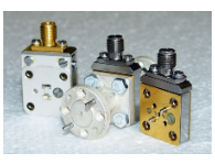
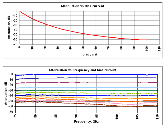
ELVA-1 series Voltage-Controlled Variable Attenuators VCVA are built on the base of PIN diodes as an active element. Modern technology allows to combine advantages of different types of attenuators and modulators in one device. Full band operation, accuracy, 60 dB attenuation range and small insertion losses are comparable with specification for polarization attenuators. On the other hand a small switching time allows to use the device instead of Faraday rotation ferrite modulators or ON/OFF type p-i-n modulators. The attenuators are designed as a gold covered waveguide section and have a high reliability. The basic unit is a current controlled attenuator. We propose also an external driver which provides a voltage current conversion and a switching time up to the 25 μs. We supply each device with personal calibration characteristics. Typical characteristics for the VCVA-10 model are shown on two plots below: attenuation versus control voltage with fixed frequency and attenuation versus frequency with different control voltages.
| Model | VCVA-42 | VCVA-28 | VCVA-22 | VCVA-19 | VCVA-15 | VCVA-12 | VCVA-10 | VCVA-08 | VCVA-06 |
| Frequency Band | K | Ka | Q | U | V | E | W | F | D |
| Range, GHz | 18-26.5 | 26-40 | 33-50 | 40-60 | 50-75 | 60-90 | 75-110 | 90-140 | 110-170 |
| Bandwidth, % | 20 | 15 | 15 | 15 | 15 | 15 | 15 | 15 | 15 |
| Insertion Loss, dB (typ) | 0.7 | 0.7 | 0.8 | 0.8 | 0.8 | 1 | 1 | 1 | 1 |
| Isolation, dB (min) | 50* | 50* | 50* | 50* | 50* | 50* | 50* | 50* | 50* |
| Peak Power, W(max) | 1 | 1 | 1 | 1 | 1 | 1 | 1 | 1 | 1 |
| Switching Time, μs ** | 100 | 50 | 50 | 50 | 50 | 50 | 25 | 25 | 25 |
| DC Bias Input, mA | 100 | 100 | 100 | 100 | 100 | 100 | 100 | 100 |
| Bandwidth, % | 100 | 100 | 100 | 100 | 100 | 100 | 100 | 100 | 100 |
| Insertion Loss | 1.0 | 1.8 | 2 | 2 | 2 | 2 | 2 | 3 | 3 |
| Isolation, dB (min) | 50* | 50* | 50* | 50* | 50* | 50* | 50* | 50* | 45* |
| Peak Power, W(max) | 1 | 1 | 1 | 1 | 1 | 1 | 1 | 1 | 1 |
| Switching Time, μs ** | 100 | 50 | 50 | 50 | 50 | 50 | 25 | 25 | 25 |
| DC Bias Input, mA | 100 | 100 | 100 | 100 | 100 | 100 | 100 | 100 | 10 |
Voltage Controlled Variable Attenuators up to 170 GHz Datasheet
You may also like