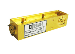
ELVA-1 Waveguide Directional Couplers
See full specification tab below or
At a glance: Key parameters
ELVA series DC-XX 3-port directional couplers are available in six waveguide bands from 50 to 220 GHz. The standard coupling levels are 3, 6, 10, 20, 30 and 40 dB with full waveguide operational bandwidth. ELVA directional couplers have directivity of up to 40 dB for frequencies below 110 GHz and 30 dB for upper frequencies.
Directional couplers are in common use for the purpose of transmitting power into a waveguide circuit without perturbing the operating characteristics of the circuit. These couplers are particularly suitable for frequency monitoring and measurement of RF power (transmitted or reflected) in circuits. Directional couplers are used for scalar network analyzers, and for signal sampling in instruments or subsystems.
The directional couplers can be used in different high-frequency equipment. They are used for dividing input signals into multiple output signals with minimum loss of power (forward direction). The standard directional couplers have 3 ports.

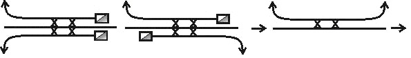
Producing of other directional couplers is possible upon special request. Energy transfer can be done from any port to any directions (it depends on the purpose of the device). The examples are the following:
In practice, the most popular models have 3 ports. The basic function of a 3-port directional coupler is to operate on an input (P1) so that two output signals (P2 and P3) are available. The output signals are unequal in amplitude. The larger signal is at the mainline output port (P2). The smaller signal is at the secondary port (P3).
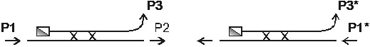
If the input signal (P1*) is applied to the opposite port (power is transmitted in the back direction) some part of the power is reflected to the opposite direction in secondary waveguide. It is possible to measure it as P3*. The difference in dB of the output power P3 and P3* is called directivity.
Main characteristics of the directional couplers
| Transmission | = 10Log(P2/P1) |
| Coupling value | = 10Log(P3/P1) |
| Insertion losses | = 10Log((P2+P3)/P1) |
| Directivity | = 10Log(P3/P3*), P1*= P1 |
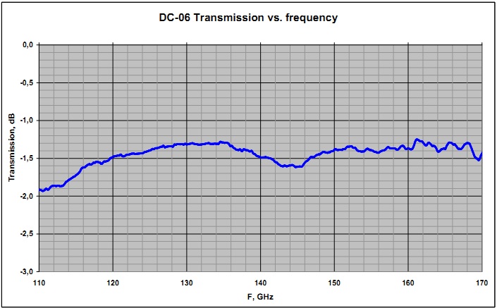
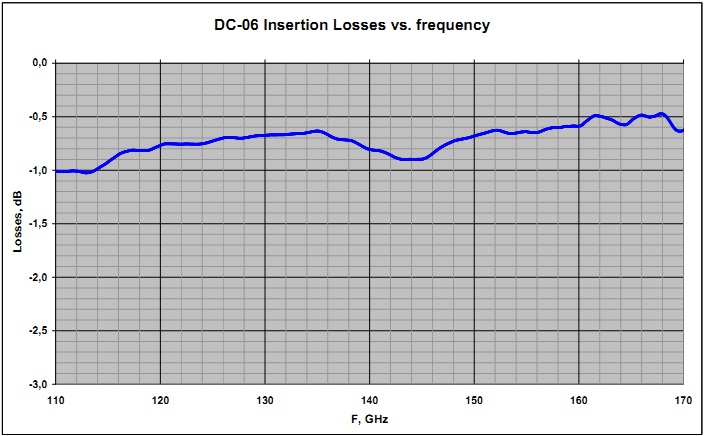
Typical directional couplers data presented in plots below:
Specifications
| MODEL NUMBER | DC-15 | DC-12 | DC-10 | DC-08 | DC-06 | DC-05 |
| Frequency range | 50-75 GHz | 60-90 GHz | 75-110 GHz | 90-140 GHz | 110-170 GHz | 140-220 GHz |
| Waveguide | WR-15 | WR-12 | WR-10 | WR-08 | WR-06 | WR-05 |
| Coupling value dB | 3, 6, 10, 20, 30, 40 | 3, 6, 10, 20, 30, 40 | 3, 6, 10, 20, 30, 40 | 3, 6, 10, 20, 30, 40 | 3, 6, 10, 20, 30 | 3, 6, 10, 20 |
| Insertion losses | 0.8 dB | 0.9 dB | 1.0 dB | 1.2 dB | 1.4 dB | 1.5 dB |
| Directivity dB | 30-40 | 30-40 | 30-40 | 30-35 | 30-35 | 25-30 |
| VSWR | 1.08:1 | 1.1:1 | 1.15:1 | 1.2:1 | 1.25:1 | 1.4:1 |
You may also like