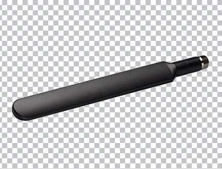
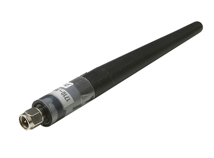
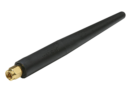
Anritsu Isotropic Antenna 2000-1792-R
See full specification tab below or
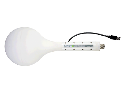
Isotropic antennas are required to perform ElectroMagnetic Field (EMF) Measurements. The E-Field isotropic antenna with tri-axis sensor and an integrated RF switch covers 30 MHz to 3 GHz
The 2000-1792-R isotropic antenna is a tri-axis E-Field sensor with an integrated RF switch. The RF switch is controlled by the analyzer via a USB port.
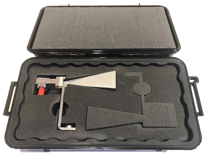
Each antenna is individually characterized and comes with a certificate of conformance and supporting test data.
- Integrated solution for Electromagnetic Field Strength measurements for health and safety
- Wide dynamic range
- Fast switching time
- Automatic download of antenna factors
- Various demodulation options available
In order to conduct EMF measurements, an Anritsu isotropic antenna is required. Anritsu offers the 2000-1792-R isotropic antenna for use with the Electromagnetic Field Measurement System. The 2000-1792-R operates over a frequency range of 30 MHz to 3 GHz. This antenna is a tri-axis E-Field sensor with an integrated RF switch device, microcontroller, and memory. Each of the three sensors is situated orthogonally inside the antenna housing to transmit and receive a spherical radiation pattern. In this way, all radiation at the antenna’s geographical position is measured, regardless of direction of arrival.
The RF switch, microcontroller, and memory inside the antenna are controlled by firmware in the Spectrum Analyzer via a USB cable. The microcontroller operates the RF switch, controlling which probe is active. Once all three probes are switched, a composite RMS calculation is made. The memory inside the antenna is used to store parameters associated with that particular antenna. This includes serial number, date of calibration, antenna frequency range, and antenna factors.
Each isotropic antenna is individually characterized over its entire frequency range. The antenna factors are stored in the antenna’s memory and automatically downloaded into the Spectrum Analyzer once the antenna USB cable is inserted.
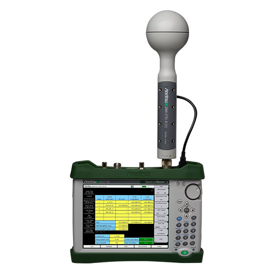
EMF Option 0444, when mated together with an Anritsu handheld spectrum analyzer (MS2711E/12E/13E, MS2720T or MT8213E) and an Anritsu isotropic antenna, provides a complete solution for EMF measurements. Option 0444 allows you to verify compliance with both national and international specifications relating to radiation safety. Each isotropic antenna provided with this system is individually characterized to insure measurement accuracy. Firmware version 1.56 or later is required for the MS2711E/12E/13E and MT8213E. For the MS2720T, firmware version 1.12 or later is required. For the MS2090A, firmware version V2020.4.1 or later is required.
The EMF option is highly automated, allowing the user to configure tests quickly and efficiently. Most features needed for test setup are available from two selection menus. Additionally, the display provides continual updates during test with pass/fail criteria set by the user. When GPS Option 31 is purchased, the EMF system also provides location awareness capabilities for the measurements. Saved test data can be stamped as a function of location.
Additional features provided by Option 0444 include the provision of limit line capability. Users can set multiple thresholds over a wide frequency range to trigger alarms for high radiation events. These limit lines can be saved and recalled at a later time for reuse. Automatic save features allow for easy storage of measurement results to memory. All data saved is preserved in spreadsheet format for easy post-processing and report formatting. Other configuration options include measurement test time and axis dwell time (time each axis X, Y and Z measures radiation before switching to the next axis).
EMF Measurements on Demodulated Signals
The EMF measurement system can be used to make radiation power measurements in Spectrum Analyzer mode. These are power measurements for either narrowband or wideband field strength measurements across the frequency range of the Spectrum Analyzer and isotropic antenna used. Additionally, EMF testing can be conducted on demodulated signals for various cellular standards. These include the LTE, TD-LTE and W-CDMA standards.
To measure demodulated W-CDMA signals, Option 0035 is required for the MS2712E/13E and MT8213E platforms. For MS2720T, Option 0081 is required for W-CDMA. Option 0009 is also required for the MS2712E/13E and MS2720T platforms for W-CDMA demodulation capability. The field strength of the pilot channel (P-CPICH) is measured for all such signals present. Results are then displayed for each individual scrambling code as well as for total power levels for all measurements combined. Additionally, the analog signal strength across the channel is measured and displayed for comparison. In order to present a “worst case” result, extrapolation factors can be automatically calculated and displayed where a fully loaded traffic channel is assumed.
For LTE and TD-LTE, Options 0546 and 0556 respectively are required for the MS2712E/13E and MT8213E platforms. Option 0083 is required for either LTE or TD-LTE on the MS2720T platform. Option 0009 is also required for the MS2712E/13E and MS2720T platforms for LTE or TD-LTE demodulation capability. Primary Synchronization Signals (P-SS), Secondary Synchronization Signals (S-SS) and Reference Signals (RS) are measured and displayed based on each Cell ID received. The total radiation field resulting from all cell site signals combined is calculated and displayed. The analog signal strength across the channel is measured and displayed for comparison. In order to present a “worst case” result, extrapolation factors can be automatically calculated and displayed where a fully loaded traffic channel is assumed.
You may also like